

Cold Weather Fix: Keeping the Gulper Pump Alive
One of the ongoing challenges with the BeagleBus in cold weather has been uneven heat distribution.
The furnace is located toward the rear of the camper, and by the time warm air travels forward through the ducting, much of that heat has already been lost. The front portions of the camper — particularly the Gulper pump and electronics bay — consistently run much colder than the main living area.
Because of the camper’s layout, the Gulper pump is located outside the primary wet bay in its own electronics compartment at the end of one of the longest furnace duct runs. Over time, this has made that area noticeably vulnerable during cold-weather trips.
I’ve had to replace the Gulper pump twice. Both failures occurred on very cold days. While I can’t say with certainty that freezing caused those failures, the timing strongly suggests that low temperatures may have played a role.
The nearby battery compartment also tends to run cold in winter conditions, sometimes dropping below ideal charging temperatures when relying on alternator charging.
Rather than adding additional heaters, the problem increasingly looked like an airflow issue.
So I ran a simple experiment.
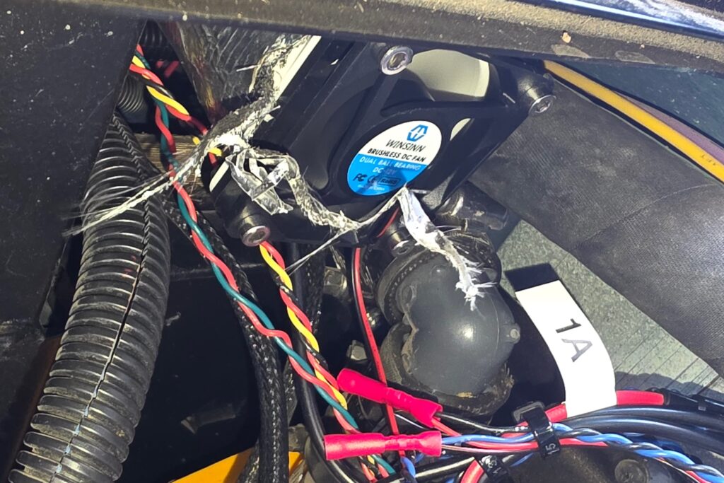
I temporarily connected a small PC fan to the end of the furnace duct feeding that compartment to see whether actively pulling warm air forward would make a measurable difference. The result was immediate — temperatures in the bay increased by roughly 30–40°F.
That confirmed the furnace was producing enough heat.
It simply wasn’t reaching the areas that needed it most.
From there, the logical next step was automation.
The Goal
Build a system that could:
- Monitor temperatures in critical areas
- Automatically pull warm air toward colder zones
- Reduce the likelihood of cold-weather failures
- Operate entirely from the camper’s native 12V system
- Be monitored and adjusted from a phone
The result is the Heat Boost Controller.
Camper Modification — Heat Boost Controller (12V DC)
Status: Installed and operational
Location: Gulper Pump & Electronics Bay
Static IP: 192.168.1.50
Objective
Improve heat delivery to vulnerable areas by automatically redistributing furnace heat where needed.
Primary goals:
- Prevent freezing in the Gulper pump electronics bay
- Help maintain warmer battery temperatures in extreme cold
- Improve forward heat distribution
- Eliminate manual intervention during freezing conditions
System Overview
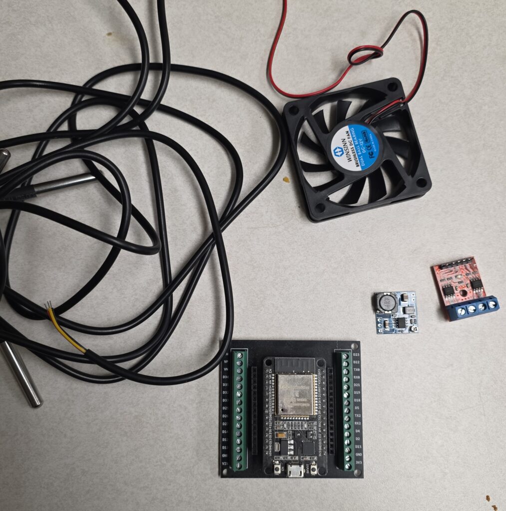
A custom ESP32-based controller monitors temperatures and activates booster fans automatically.
Operating Modes:
- AUTO Mode — temperature-driven operation
- MANUAL Mode — direct fan control via web interface
A locally hosted Wi-Fi webpage provides monitoring and adjustment.
Temperature Sensors
Three DS18B20 digital sensors share a OneWire bus.
| Sensor | Location | Purpose |
|---|---|---|
| Gulper Sensor | Gulper pump electronics bay (zip-tied to plumbing line) | Freeze protection |
| Cab Sensor | Front cab area | Heat balance |
| Duct Sensor | Furnace duct | Prevent cold-air boosting |
Fan Control
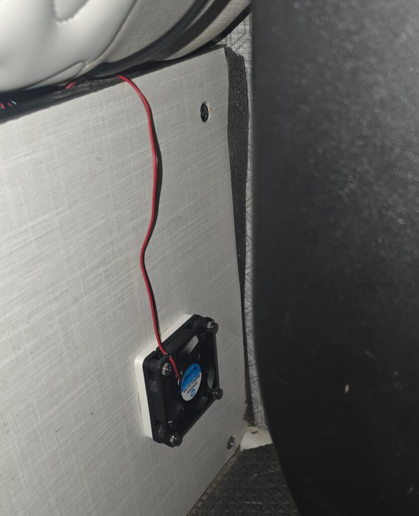
Two 12V booster fans controlled through a dual motor driver.
| Fan | Function |
|---|---|
| Fan A | Gulper bay heat boost |
| Fan B | Cab airflow assist |
Fans activate automatically using temperature thresholds, hysteresis, and anti-chatter timing.
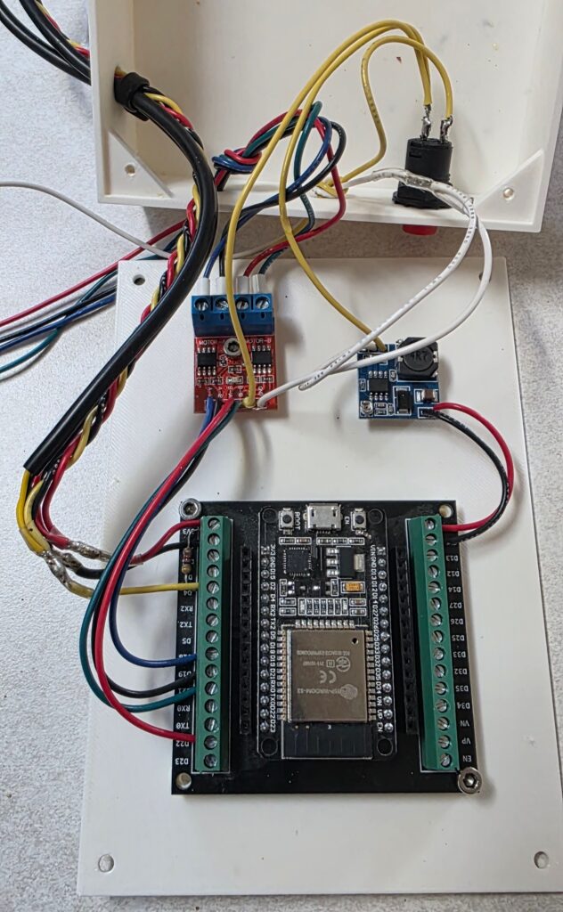
Power Architecture
- Camper 12V supply
- Inline fused input (1A installed)
- Buck converter → regulated 5V logic supply
- ESP32 powered from 5V rail
- Fans powered directly from 12V
- Shared system ground
System verified stable between 12–14.4V vehicle voltage.
Network Interface
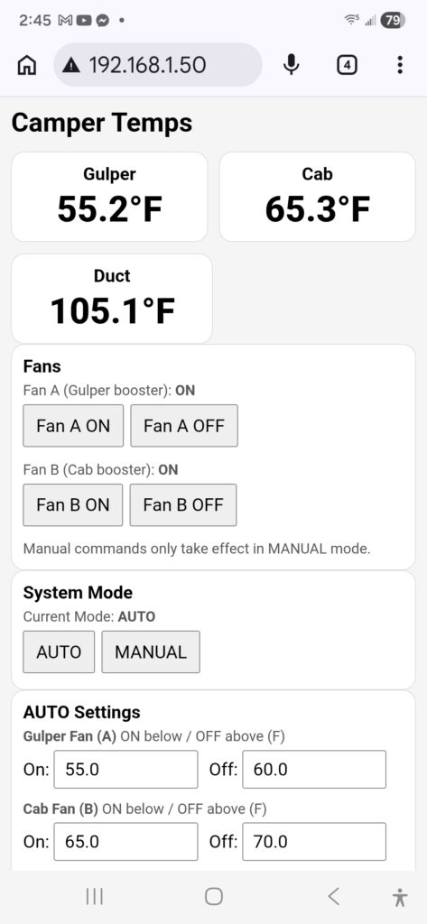
Controller hosts onboard web server.
Accessible via Starlink network:
http://192.168.1.50
Displays:
- Gulper temperature
- Cab temperature
- Duct temperature
- Fan status
- System mode
- AUTO thresholds
Enclosure
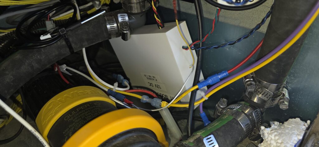
Custom ABS control box installed in Gulper electronics bay.
Features:
- Hard-soldered wiring
- Labeled sensors and fans
- Fused input
- Serviceable terminals
- Permanent installation
Exterior label:
HEAT BOOST CONTROLLER
12V DC
192.168.1.50
Failure Modes & Recovery Notes
No Web Page / Cannot Connect
Symptoms
- IP address unreachable
Likely Causes
- Power loss
- Blown fuse
- Buck converter failure
- Router reboot
Recovery
- Verify Wi-Fi active
- Check controller power LED
- Inspect fuse
- Confirm 5V output
- Power cycle controller
Fans default OFF safely.
Fans Not Running in AUTO
Likely Causes
- MANUAL mode active
- Threshold settings incorrect
- Duct gate active
- Sensor reading invalid
Recovery
Verify AUTO mode and threshold settings.
Fans Run Continuously
Likely Causes
- Sensor exposed to cold airflow
- Threshold reversal
- Sensor fault
Confirm:
OFF temperature > ON temperature
Incorrect Temperature Readings
Likely Causes
- Sensor wiring issue
- Moisture intrusion
- Bus connection failure
Inspect wiring and reboot controller.
Fuse Blows
Likely Causes
- Fan short
- Wiring damage
- Driver fault
Disconnect fans and reconnect individually.
Recommended range:
- 1A normal
- 2A if nuisance trips occur
Controller Lockup (Rare)
Recovery
Power-cycle controller.
Future upgrade: watchdog reboot.
Cold Weather Limitation
The system redistributes furnace heat.
It does not generate additional heat.
Extremely low ambient temperatures may still require increased furnace runtime.
Safe Failure Behavior
If controller fails:
- Fans turn OFF
- Furnace unaffected
- No risk to primary heating system
Result
System installed and tested successfully.
Bench testing confirms:
- Temperature monitoring functional
- Web interface operational
- Automatic fan control operational
- Significant temperature increase achievable in Gulper bay
Final validation pending sustained sub-freezing field use.